
Good vertex data layout and compression is integral to the performance of any graphical application, whether an app consists of 2D user interfaces or is a large 3D open world game. Internal testing with Android GPU Inspector’s Frame Profiler on dozens of top Android Games indicates that much could be done to improve vertex data management. We have observed that it's common for vertex data to use full precision, 32-bit float values for all vertex attributes, and a vertex buffer layout that uses an array of structures formatted with fully interleaved attributes.
This article discusses how to optimize the graphics performance of your Android application by using the following techniques:
- Vertex Compression
- Vertex Stream Splitting
Implementing these techniques can improve vertex memory bandwidth usage by up to 50%, reduce memory bus contention with the CPU, reduce stalls on system memory, and improve battery life; all of which are wins for both developers and end users!
All data presented comes from an example static scene containing ~19,000,000 vertices running on a Pixel 4:
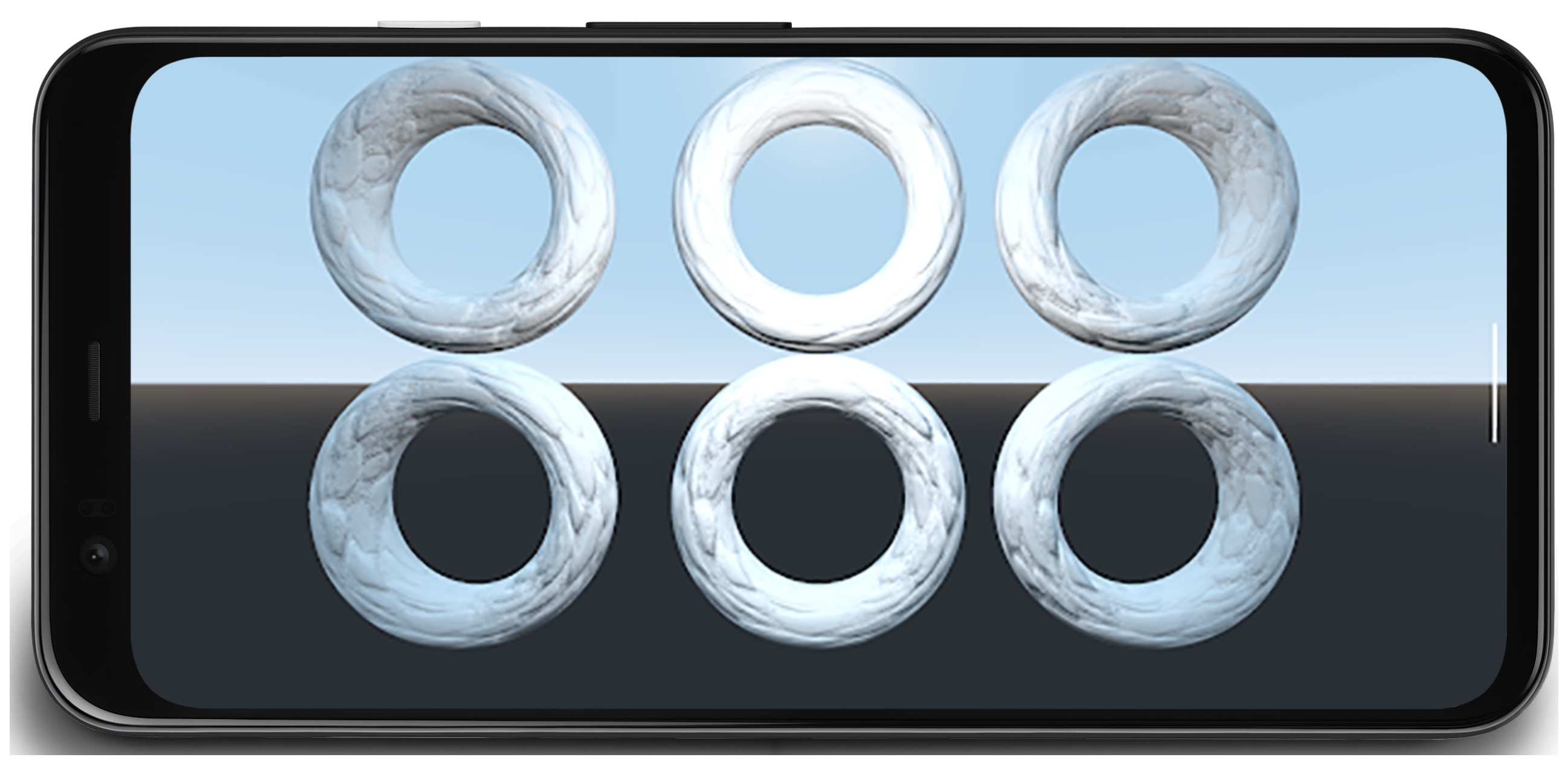
Figure 1: Sample scene with 6 rings and 19m vertices
Vertex compression
Vertex Compression is an umbrella term for lossy compression techniques that use efficient packing to reduce the size of vertex data both during runtime and in storage. Reducing the size of vertices has several benefits, including reducing memory bandwidth on the GPU (by trading compute for bandwidth), improving cache utilization, and potentially reducing the risk of spilling registers.
Common approaches to Vertex Compression include:
- Reducing the numerical precision of vertex data attributes (ex: 32-bit float to 16-bit float)
- Representing attributes in different formats
For example, if a vertex uses full 32-bit floats for position (vec3), normal (vec3), and texture coordinate (vec2), replacing all of these with 16-bit floats will reduce vertex size by 50% (16 bytes on an average 32 byte vertex).
Vertex positions
Vertex position data can be compressed from full precision 32-bit floating point values to half precision 16-bit floating point values in the vast majority of meshes, and half floats are supported in hardware on almost all mobile devices. A conversion function going from float32 to float16 looks like this (adapted from this guide):
uint16_t f32_to_f16(float f) {
  uint32_t x = (uint32_t)f;
  uint32_t sign = (unsigned short)(x >> 31);
  uint32_t mantissa;
  uint32_t exp;
  uint16_t hf;

  mantissa = x & ((1 << 23) - 1);
  exp = x & (0xFF << 23);
  if (exp >= 0x47800000) {
    // check if the original number is a NaN
    if (mantissa && (exp == (0xFF << 23))) {
      // single precision NaN
      mantissa = (1 << 23) - 1;
    } else {
      // half-float will be Inf
      mantissa = 0;
    }
    hf = (((uint16_t)sign) << 15) | (uint16_t)((0x1F << 10)) |
         (uint16_t)(mantissa >> 13);
  }
  // check if exponent is <= -15
  else if (exp <= 0x38000000) {
    hf = 0;  // too small to be represented
  } else {
    hf = (((uint16_t)sign) << 15) | (uint16_t)((exp - 0x38000000) >> 13) |
         (uint16_t)(mantissa >> 13);
  }

  return hf;
}
There is a limitation to this approach; precision degrades as the vertex gets farther from the origin, making it less suitable for meshes that are very large spatially (vertices that have elements that go beyond 1024). You can address this by splitting up a mesh into smaller chunks, centering each chunk around the model origin, and scaling so that all the vertices for each chunk fit within the [-1, 1] range, which contains the highest precision for floating point values. The pseudocode for compression looks like this:
for each position p in Mesh:
   p -= center_of_bounding_box // Moves Mesh back to the center of model space
   p /= half_size_bounding_box // Fits the mesh into a [-1, 1] cube
   vec3<float16> result = vec3(f32_to_f16(p.x), f32_to_f16(p.y), f32_to_f16(p.z));
You bake the scale factor and translation into the model matrix in order to decompress the vertex data when rendering. Keep in mind that you don't want to use this same model matrix for transforming normals, as they didn't have the same compression applied. You will need a matrix without these decompression transformations for normals, or you can use the base model matrix (which you can use for normals) and then apply the additional decompression transformations to the model matrix within the shader. An example:
vec3 in in_pos;

void main() {
   ...
   // bounding box data packed into uniform buffer
   vec3 decompress_pos = in_pos * half_size_bounding_box + center_of_bounding_box;
   gl_Position = proj * view * model * decompress_pos;
}
Another approach involves using Signed Normalized Integers (SNORM). SNORM data types use integers rather than floating point to represent values between [-1, 1]. Using a 16-bit SNORM for positions gives you the same memory savings as a float16 without the drawbacks of non-uniform distributions. An implementation we recommend for using SNORM looks like this:
const int BITS = 16

for each position p in Mesh:
   p -= center_of_bounding_box // Moves Mesh back to the center of model space
   p /= half_size_bounding_box // Fits the mesh into a [-1, 1] cube
   // float to integer value conversion
   p = clamp(p * (2^(BITS - 1) - 1), -2^(BITS - 1), 2^(BITS - 1) - 1)
| Format | Size | |
|---|---|---|
| Before | vec4<float32> |
16 bytes |
| After | vec3<float16/SNORM16> |
6 bytes |
Vertex normals and tangent space
Vertex Normals are needed for lighting, and the tangent space is needed for more complicated techniques such as normal mapping.
Tangent space
The tangent space is a coordinate system where every vertex consists of the normal, tangent, and bitangent vector. Because these three vectors are usually orthogonal to each other, we only need to store two of them and can calculate the third by taking a cross product of the other two in the vertex shader.
These vectors can typically be represented using 16-bit floats without any perceptual loss in visual fidelity, so that’s a good place to start!
We can compress further with a technique known as QTangents that stores the entire tangent space in a single quaternion. Since quaternions can be used to represent rotations, by thinking of the tangent space vectors as column vectors of a 3x3 matrix representing a rotation (in this case from model space into the tangent space) we can convert between the two! A quaternion can be treated as vec4 data-wise, and a conversion from tangent space vectors to a QTangent based on the paper linked above and adapted from the implementation here is as follows:
const int BITS = 16

quaternion tangent_space_to_quat(vec3 normal, vec3 tangent, vec3 bitangent) {
   mat3 tbn = {normal, tangent, bitangent};
   quaternion qTangent(tbn);
   qTangent.normalize();

   //Make sure QTangent is always positive
   if (qTangent.w < 0)
       qTangent = -qTangent;

   const float bias = 1.0 / (2^(BITS - 1) - 1);

   //Because '-0' sign information is lost when using integers,
   //we need to apply a "bias"; while making sure the Quaternion
   //stays normalized.
   // ** Also our shaders assume qTangent.w is never 0. **
   if (qTangent.w < bias) {
       Real normFactor = Math::Sqrt( 1 - bias * bias );
       qTangent.w = bias;
       qTangent.x *= normFactor;
       qTangent.y *= normFactor;
       qTangent.z *= normFactor;
   }

   //If it's reflected, then make sure .w is negative.
   vec3 naturalBinormal = cross_product(tangent, normal);
   if (dot_product(naturalBinormal, binormal) <= 0)
       qTangent = -qTangent;
   return qTangent;
}
The quaternion will be normalized, and you will be able to compress it using SNORMs. 16-bit SNORMs give good precision and memory savings. 8-bit SNORMs can provide even more savings, but may cause artifacts on highly specular materials. You can try both and see what works best for your assets! Encoding the quaternion looks like this:
for each vertex v in mesh:
   quaternion res = tangent_space_to_quat(v.normal, v.tangent, v.bitangent);
   // Once we have the quaternion we can compress it
   res = clamp(res * (2^(BITS - 1) - 1), -2^(BITS - 1), 2^(BITS - 1) - 1);
To decode the quaternion in the vertex shader (adapted from here):
vec3 xAxis( vec4 qQuat )
{
  float fTy  = 2.0 * qQuat.y;
  float fTz  = 2.0 * qQuat.z;
  float fTwy = fTy * qQuat.w;
  float fTwz = fTz * qQuat.w;
  float fTxy = fTy * qQuat.x;
  float fTxz = fTz * qQuat.x;
  float fTyy = fTy * qQuat.y;
  float fTzz = fTz * qQuat.z;

  return vec3( 1.0-(fTyy+fTzz), fTxy+fTwz, fTxz-fTwy );
}

vec3 yAxis( vec4 qQuat )
{
  float fTx  = 2.0 * qQuat.x;
  float fTy  = 2.0 * qQuat.y;
  float fTz  = 2.0 * qQuat.z;
  float fTwx = fTx * qQuat.w;
  float fTwz = fTz * qQuat.w;
  float fTxx = fTx * qQuat.x;
  float fTxy = fTy * qQuat.x;
  float fTyz = fTz * qQuat.y;
  float fTzz = fTz * qQuat.z;

  return vec3( fTxy-fTwz, 1.0-(fTxx+fTzz), fTyz+fTwx );
}

void main() {
  vec4 qtangent = normalize(in_qtangent); //Needed because 16-bit quantization
  vec3 normal = xAxis(qtangent);
  vec3 tangent = yAxis(qtangent);
  float biNormalReflection = sign(in_qtangent.w); //ensured qtangent.w != 0
  vec3 binormal = cross(normal, tangent) * biNormalReflection;
  ...
}
| Format | Size | |
|---|---|---|
| Before | vec3<float32> + vec3<float32> + vec3<float32> |
36 bytes |
| After | vec4<SNORM16> |
8 bytes |
Normals Only
If you only need to store normal vectors, there is a different approach that can lead to more savings - using Octahedral Mapping of unit vectors rather than Cartesian Coordinates to compress the normal vector. Octahedral Mapping works by projecting a unit sphere to an octahedron, and then projecting the octahedron down to a 2D plane. The result is that you can represent any normal vector using just two numbers. These two numbers can be thought of as texture coordinates we use to “sample” the 2D plane we projected the sphere onto, allowing us to recover the original vector. These two numbers can then be stored in an SNORM8.

Figure 2: Octahedral Mapping Visualized (source)
const int BITS = 8

// Assumes the vector is unit length
// sign() function should return positive for 0
for each normal n in mesh:
  float invL1Norm = 1.0 / (abs(n.x) + abs(n.y) + abs(n.z));
  vec2 res;
  if (n.z < 0.0) {
    res.x = (1.0 - abs(n.y * invL1Norm)) * sign(n.x);
    res.y = (1.0 - abs(n.x * invL1Norm)) * sign(n.y);
  } else {
    res.x = n.x * invL1Norm;
    res.y = n.y * invL1Norm;
  }
  res = clamp(res * (2^(BITS - 1) - 1), -2^(BITS - 1), 2^(BITS - 1) - 1)
Decompression in the vertex shader (to convert back to cartesian coordinates) is inexpensive; with most modern mobile devices we did not see any major performance degradation when implementing this technique. The decompression in the vertex shader:
//Additional Optimization: twitter.com/Stubbesaurus/status/937994790553227264
vec3 oct_to_vec(vec2 e):
  vec3 v = vec3(e.xy, 1.0 - abs(e.x) - abs(e.y));
  float t = max(-v.z, 0.0);
  v.xy += t * -sign(v.xy);
  return v;
This approach can also be used to store the entire tangent space, using this technique to store the normal and tangent vector using vec2<SNORM8> but you will need to find a way to store the direction of the bitangent (needed for the common scenario where you have mirrored UV coordinates on a model). One way to implement this is to map a component of your tangent vector encoding to always be positive, then flip it’s sign if you need to flip the bitangent direction and check for that in the vertex shader:
const int BITS = 8
const float bias = 1.0 / (2^(BITS - 1) - 1)

// Compressing
for each normal n in mesh:
  //encode to octahedron, result in range [-1, 1]
  vec2 res = vec_to_oct(n);

  // map y to always be positive
  res.y = res.y * 0.5 + 0.5;

  // add a bias so that y is never 0 (sign in the vertex shader)
  if (res.y < bias)
    res.y = bias;

  // Apply the sign of the binormal to y, which was computed elsewhere
  if (binormal_sign < 0)
    res.y *= -1;

  res = clamp(res * (2^(BITS - 1) - 1), -2^(BITS - 1), 2^(BITS - 1) - 1)
// Vertex shader decompression
vec2 encode = vec2(tangent_encoded.x, abs(tangent_encoded.y) * 2.0 - 1.0));
vec3 tangent_real = oct_to_vec3(encode);
float binormal_sign = sign(tangent_encode.y);
| Format | Size | |
|---|---|---|
| Before | vec3<float32> |
12 bytes |
| After | vec2<SNORM8> |
2 bytes |
Vertex UV Coordinates
UV Coordinates, used for texture mapping (among other things), are typically stored using 32 bit floats. Compressing them with 16 bit floats causes precision issues for textures larger than 1024x1024; floating-point precision between [0.5, 1.0] means that values will increment by larger than 1 pixel!
The better approach is to use unsigned normalized integers (UNORM), specifically UNORM16; this provides uniform distribution across the entire texture coordinate range, supporting textures up to 65536x65536! This assumes texture coordinates are within the range [0.0, 1.0] per element, which may not be the case depending on the mesh (for example walls can use wrapping texture coordinates that go beyond 1.0) so keep that in mind when looking at this technique. The conversion function would look like this:
const int BITS = 16

for each vertex_uv V in mesh:
  V *= clamp(2^BITS - 1, 0, 2^BITS - 1);  // float to integer value conversion
| Format | Size | |
|---|---|---|
| Before | vec2<float32> |
8 bytes |
| After | vec2<UNORM16> |
4 bytes |
Vertex Compression Results
These vertex compression techniques led to a 66% reduction in vertex memory storage, going from 48 bytes down to 16 bytes. This manifested itself as:
- Vertex Memory Read Bandwidth:
- Binning: 27GB/s to 9GB/s
- Rendering: 4.5B/s to 1.5GB/s
- Vertex Fetch Stalls:
- Binning: 50% to 0%
- Rendering: 90% to 90%
- Average Bytes/Vertex:
- Binning: 48B to 16B
- Rendering: 52B to 18B

Figure 3: Android GPU Inspector view of uncompressed vertices

Figure 4: Android GPU Inspector view of compressed vertices
Vertex Stream Splitting
Vertex Stream Splitting optimizes the organization of data in the vertex buffer. This is a cache performance optimization that makes a difference on tile-based GPUs typically found in Android Devices - in particular during the binning step of the rendering process.
Tile-based GPUs create a shader that calculates the normalized device coordinates based on the provided vertex shader to do binning. It is executed first on every vertex in the scene, whether visible or not. Keeping vertex position data contiguous in memory is therefore a big plus. Other places this vertex stream layout can be beneficial is for shadow passes, as usually you only need position data for shadow calculations, as well as depth prepasses, which is a technique usually used for console/desktop rendering; this vertex stream layout can be a win for multiple classes of the rendering engine!
Stream Splitting involves setting up the vertex buffer with a contiguous section of vertex position data and another section containing interleaved vertex attributes. Most applications usually set up their buffers fully interleaving all attributes. This visual explains the difference:
Before:
|Position1/Normal1/Tangent1/UV1/Position2/Normal2/Tangent2/UV2......|

After:
|Position1/Position2...|Normal1/Tangent1/UV1/Normal2/Tangent2/UV2...|
Looking at how the GPU fetches vertex data helps us understand the benefits of stream splitting. Assuming for the sake of argument:
- 32 byte cache lines (a pretty common size)
- Vertex format consisting of:
- Position, vec3<float32> = 12 bytes
- Normal vec3<float32> = 12 bytes
- UV coordinates vec2<float32> = 8 bytes
- Total size = 32 bytes
When the GPU fetches data from memory for binning, it will pull a 32-byte cache line to operate on. Without vertex stream splitting, it will only actually use the first 12 bytes of this cache line for binning, and discard the other 20 bytes as it fetches the next vertex. With vertex stream splitting, the vertex positions will be contiguous in memory, so when that 32-byte chunk is pulled into cache, it will actually contain 2 whole vertex positions to operate on before having to go back to main memory to fetch more, a 2x improvement!
Now, if we combine the vertex stream splitting with vertex compression, we will reduce the size of a single vertex position down to 6 bytes, so a single 32-byte cache line pulled from system memory will have 5 whole vertex positions to operate on, a 5x improvement!
Vertex Stream Splitting Results
- Vertex Memory Read Bandwidth:
- Binning: 27GB/s to 6.5GB/s
- Rendering: 4.5GB/s to 4.5GB/s
- Vertex Fetch Stalls:
- Binning: 40% to 0%
- Rendering: 90% to 90%
- Average Bytes/Vertex:
- Binning: 48B to 12B
- Rendering: 52B to 52B
Figure 5: Android GPU Inspector view of unsplit vertex streams

Figure 6: Android GPU Inspector view of split vertex streams
Compound Results
- Vertex Memory Read Bandwidth:
- Binning: 25GB/s to 4.5GB/s
- Rendering: 4.5GB/s to 1.7GB/s
- Vertex Fetch Stalls:
- Binning: 41% to 0%
- Rendering: 90% to 90%
- Average Bytes/Vertex:
- Binning: 48B to 8B
- Rendering: 52B to 19B
Figure 7: Android GPU Inspector view of unsplit, uncompressed vertex streams

Figure 8: Android GPU Inspector view of split, compressed vertex streams
Additional Considerations
16 vs 32 bit Index Buffer Data
- Always split/chunk meshes so that they fit into a 16-bit index buffer (max 65536 unique vertices). This will help with indexed rendering on mobile as it’s cheaper to fetch vertex data and will consume less power.
Unsupported Vertex Buffer Attribute Formats
- SSCALED vertex formats are not widely supported on mobile, and when used can have costly performance trade-offs in drivers that try to emulate them if they don’t have hardware support. Always go for SNORM and pay the negligible ALU cost to decompress.