
Android devices are available in a variety of form factors and screen sizes. Common categories include:
- Mobile phones
- Tablets
- Televisions and television set-top boxes
- Laptops with Android Runtime for Chrome
This variety means your game will encounter a range of different screen resolutions, often with different aspect ratios. For example:
- A phone in landscape orientation with a 19:9 aspect ratio (2280x1080)
- A different phone in landscape orientation with a 20:9 aspect ratio (3200x1400)
- A 1080p HD TV with a 16:9 aspect ratio (1920x1080)
- A tablet with a 4:3 aspect ratio (2048x1536)
The design of your game should take these differences into account to ensure correct presentation regardless of the screen resolution and aspect ratio of the device.
Defold projection modes
A Defold project has a configurable base resolution. This resolution is set in
the game.project file using the Width and Height fields in the Display category.
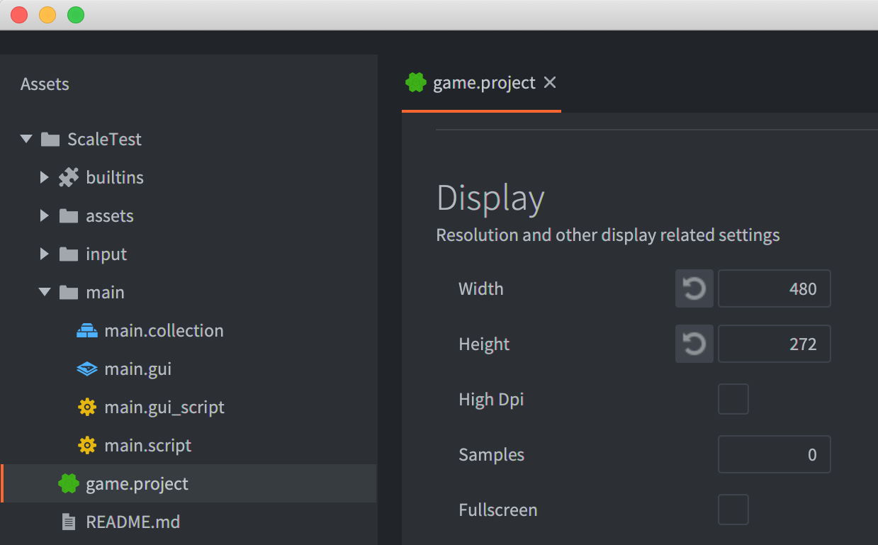
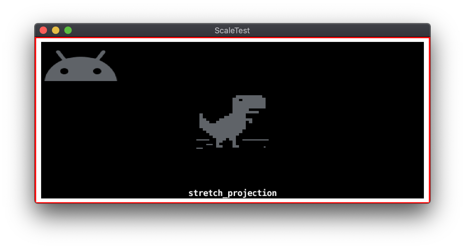
The default behavior of Defold is to render at the base resolution and then scale the resulting image to the actual resolution of the target device. Defold refers to this mode as stretch projection. Stretch projection does not preserve the original aspect ratio. For some games, this default may be visually acceptable. The standard Defold rendering script includes two additional projection options that preserve the base aspect ratio: fixed fit projection and fixed projection.
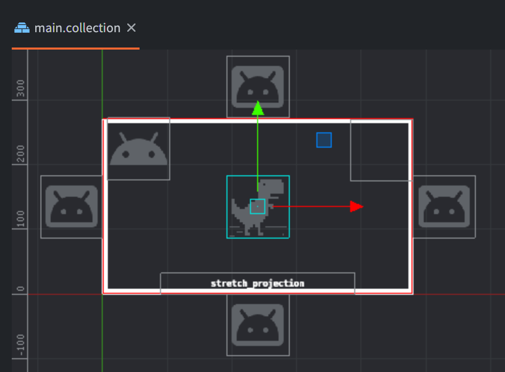
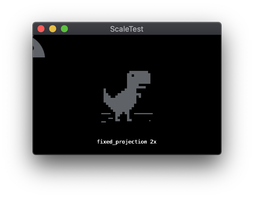
The following example shows a sample project designed around a base resolution of 480x272, displayed in the Defold editor.
In this example:
- A tilemap object is used to draw a frame around the borders of the base resolution.
- Two sprite objects and a text object are located inside the bounds of the base resolution.
- There are four sprite objects positioned outside the bounds of the base resolution, above, below, left, and right respectively.
When run at a display resolution of 960x544, exactly 2x the base resolution, the project displays as follows:
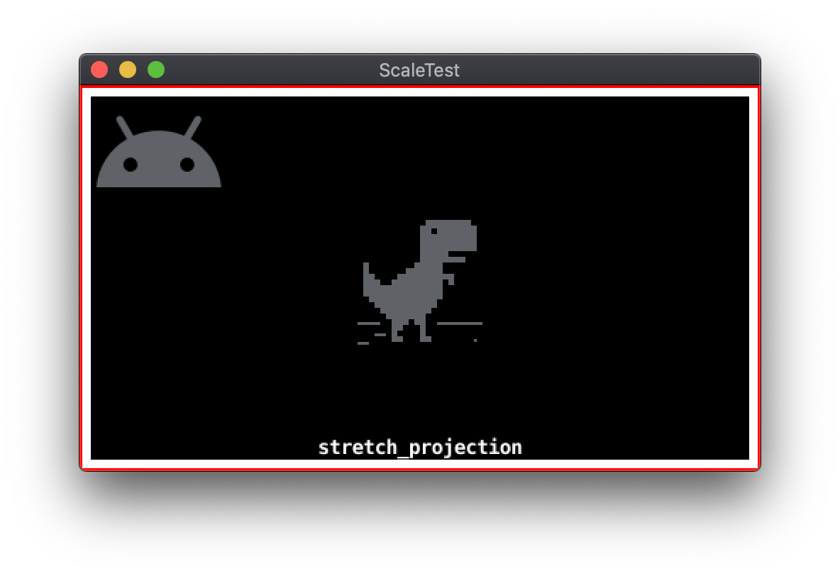
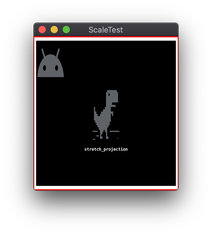
Stretch projection
The following examples show the results of resizing the window with default stretch projection, where the aspect ratio is not preserved:
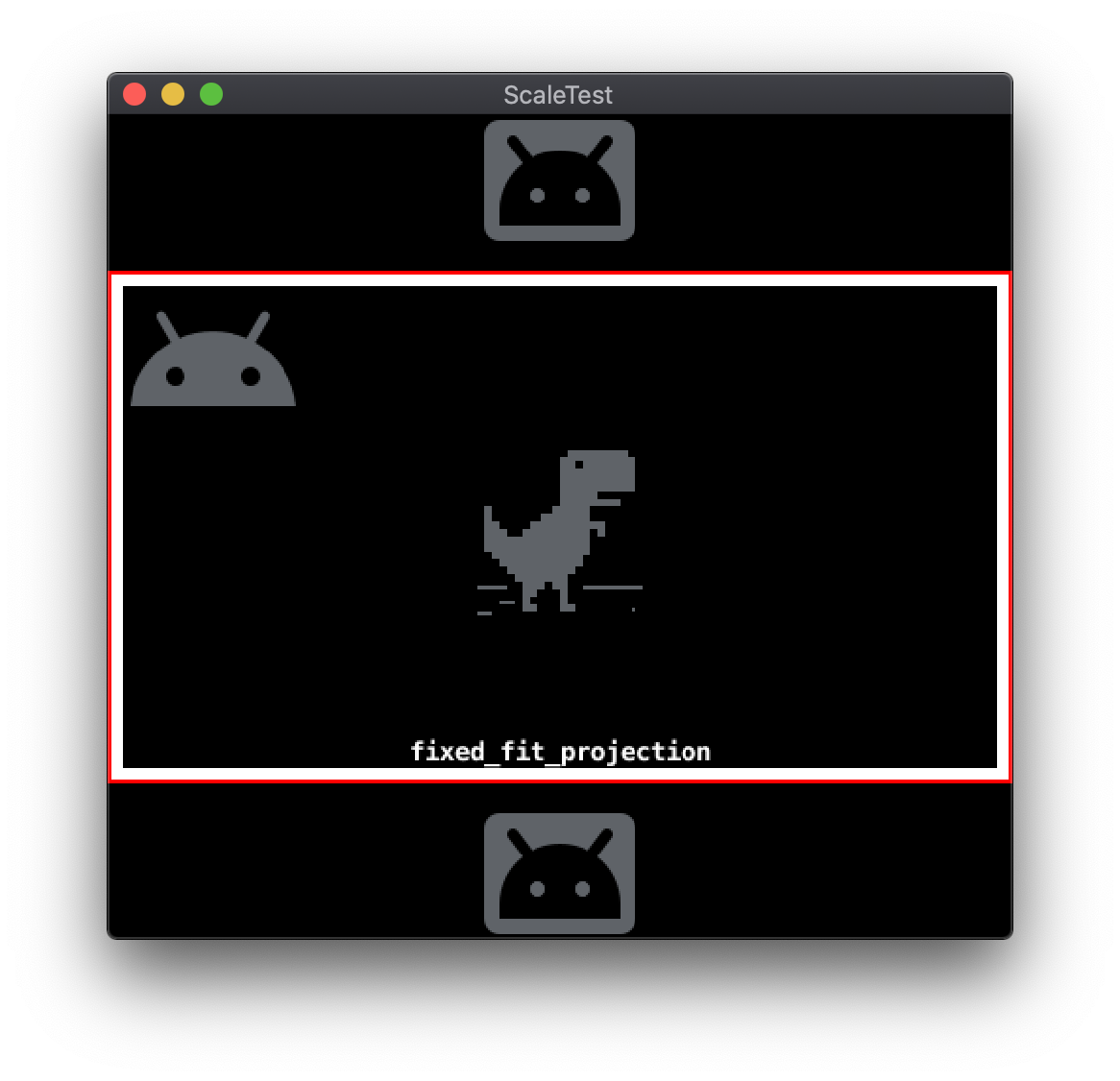
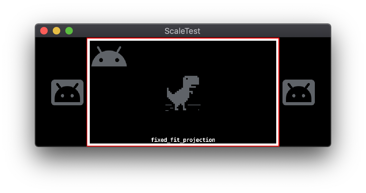
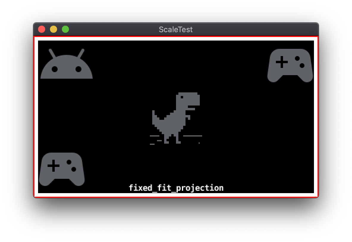
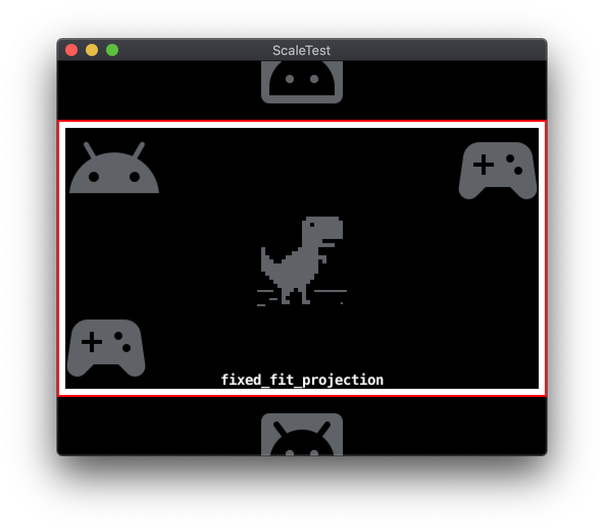
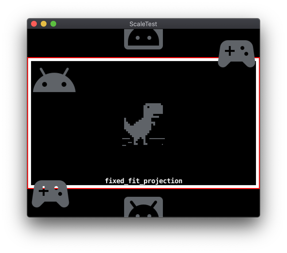
Fixed-fit projection
The fixed-fit projection mode maintains the base resolution aspect ratio. Because the aspect ratio is preserved, there will be additional screen area not covered by the scaled base resolution. Depending on the major axis of the aspect ratio difference, this extra area exists either at the top and bottom or the left and right of the base resolution. Fixed-fit projection will modify the base resolution to account for this area. This modification results in additional areas of the game scene outside of the base resolution region being rendered. The resulting image is then scaled to the display resolution.
The following examples demonstrate fixed-fit projection rendering to a display resolution with a different aspect ratio than the base resolution of 480x272:
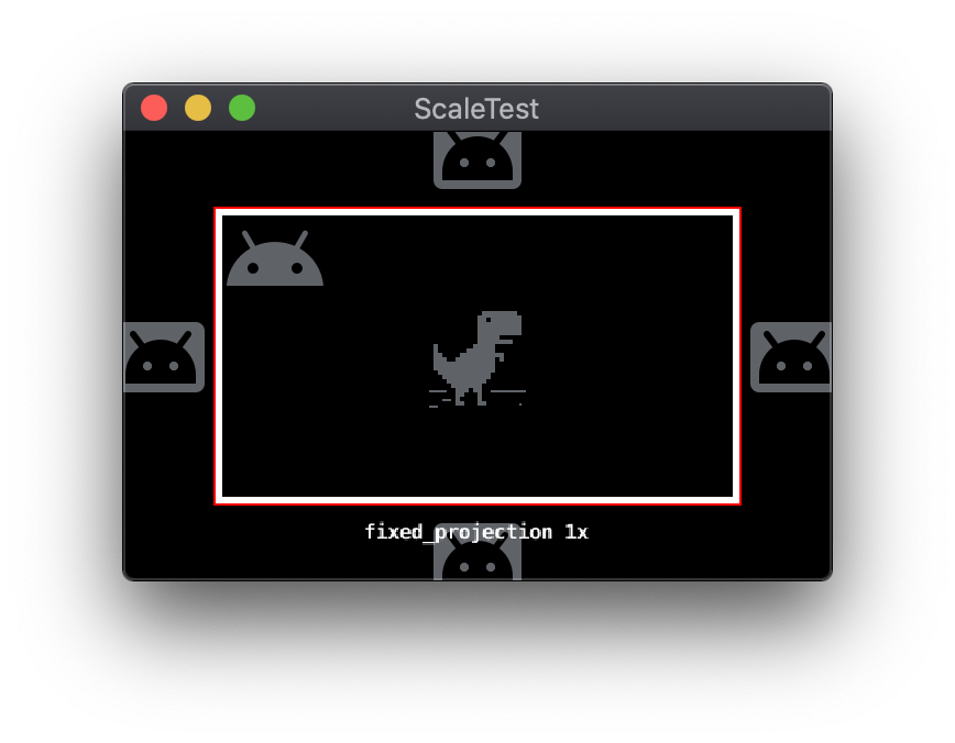
Fixed projection
The fixed projection mode maintains the base resolution aspect ratio and scales the base resolution by a specified zoom factor. Depending on the display resolution and the zoom factor, a subset or superset of the base resolution area may be displayed.
The following examples demonstrate fixed projection mode using a screen resolution of 644x408 with 1x and 2x zoom factors, respectively:
Change projection modes
The active projection mode can be switched at runtime by sending the appropriate message to the renderer. These messages are sent using the standard Defold message system. All projection mode messages include parameters specifying near and far plane Z values.
-- Change to stretch projection mode
msg.post("@render:", "use_stretch_projection", { near = -1, far = 1 })

-- Change to fixed fit projection mode
msg.post("@render:", "use_fixed_fit_projection", { near = -1, far = 1 })

-- Change to fixed projection mode
msg.post("@render:", "use_fixed_projection", { near = -1, far = 1, zoom = 2 })
Defold render scripts
Defold rendering behavior is controlled by a special script file called a render script. Like other Defold Engine scripts, the render script is written in the Lua programming language. A default render script is included at project creation, but you can also replace it with a custom render script.
The stretched, fixed-fit and fixed projection modes are features of the default render script. When using one of these modes, the render script generates a 2D orthographic projection matrix for use in rendering game objects. The configuration of this matrix differs depending on the projection mode being used.
You can use a custom render script to extend or change the configuration of the projection matrix. Functionality not supported by the default script, such as letterboxes or pillarboxes for different aspect ratios, can also be implemented with custom render scripts.
Open-source developers have created render script and camera packages that offer more features than the default Defold scripts. Two commonly-used packages are RenderCam and Defold-Orthographic.
Defold GUI system
Defold includes a GUI system, based around the concept of GUI scene files. GUI scene files include objects called nodes that define individual UI elements such as images or text.
GUI scene files can be added as a component to a Defold game object. GUI scenes and their included nodes are rendered separately and work slightly differently from normal game objects. Because of these differences, supporting multiple display resolutions with GUI scenes involves additional considerations related to GUI system coordinates and GUI node pivots and anchors.
GUI system coordinates
Normal Defold game objects specify their coordinates in world space. A camera object translates world space to screen space and displays the game objects that fall within the camera’s current virtual view. The GUI system uses its own separate camera. Nodes belonging to a GUI scene use screen space coordinates instead of world space coordinates. When the display resolution differs from the project base resolution used to layout the GUI nodes, this can result in nodes having differing margins relative to screen edges or the edges of a parent node. Defold has multiple options for making GUI layout adjustments to account for differences in display resolution.
GUI node pivot and anchors
GUI nodes can be anchored to vertical and/or horizontal edges using the X Anchor and Y Anchor properties.
- If a node has a parent node, the anchor is to the edges of the parent node.
- If a node has no parent node, the anchor is to the edges of the screen.
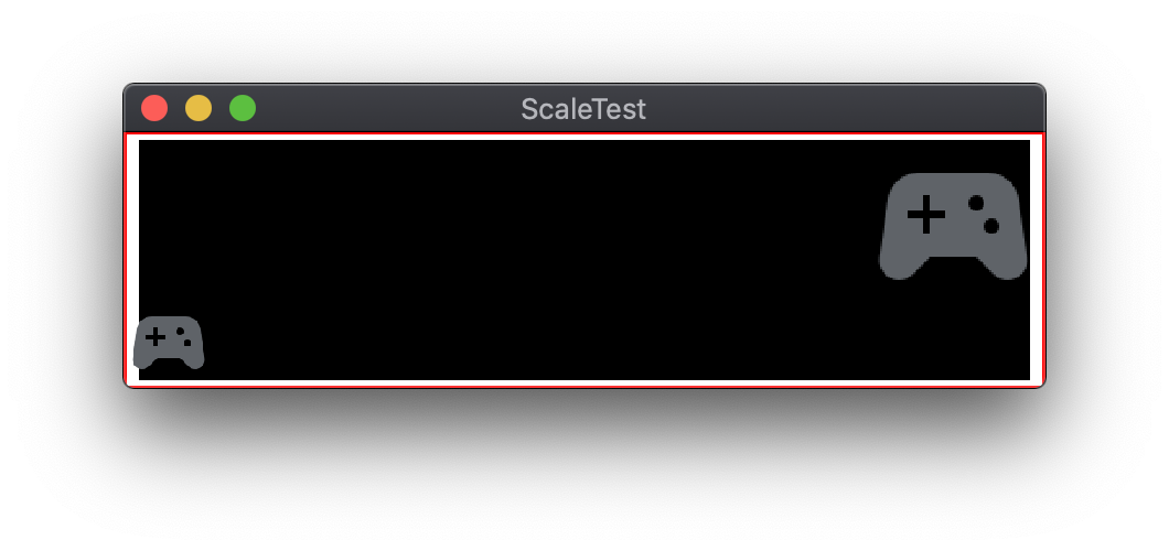
The following illustrates a sample scene with two GUI nodes, the controller
icons in the bottom-left and top-right corners. Both nodes have X Anchor and
Y Anchor set to None:
When the display is resized without an anchor, the controller icons maintain their positions relative to the base resolution:
NoneWhen the Y Anchor of the bottom-left node is set to Bottom and the
Y Anchor of the top-right node is set to Top, the GUI nodes will anchor
to the appropriate screen edges:
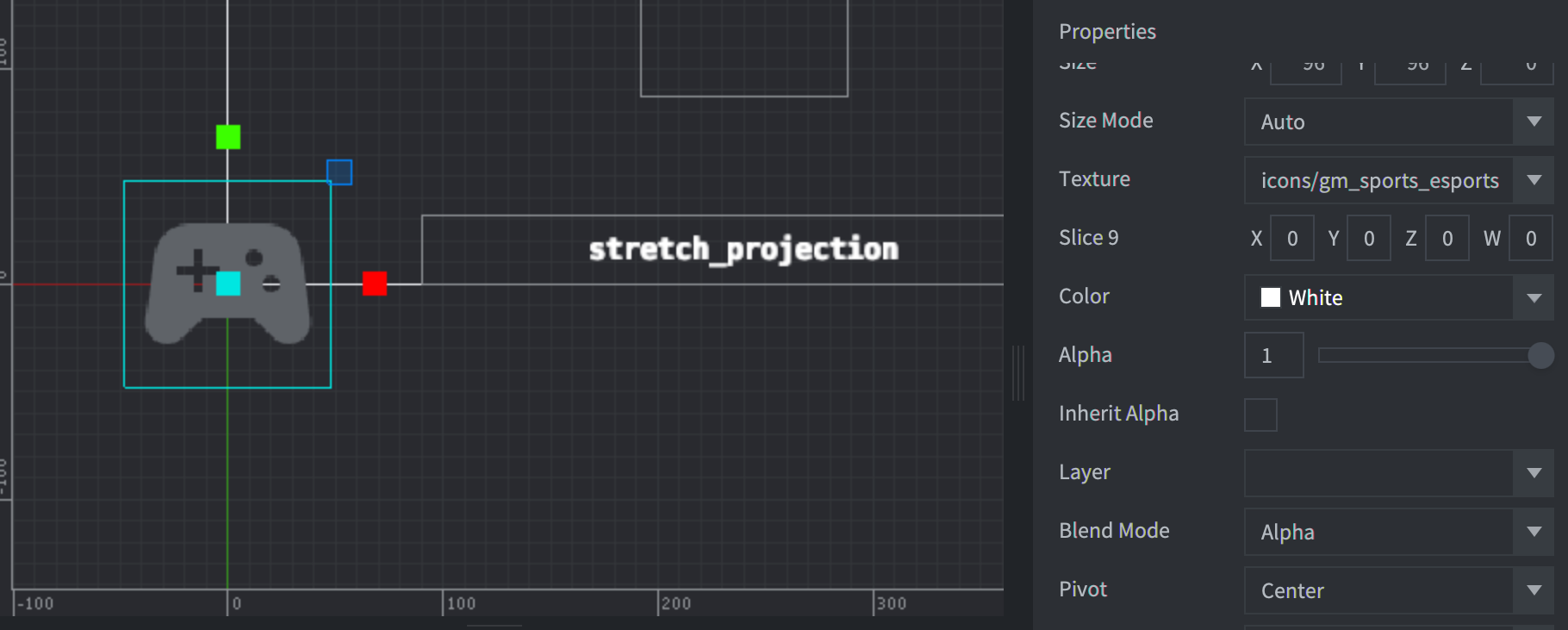
EdgesThe Pivot property of a GUI node specifies the point on the node’s bounds
rectangle that corresponds with its screen-space coordinate Position
property. GUI nodes default to the Center setting, placing its Position
point in the direct center of the bounds rectangle. Other possible Pivot
settings include the four cardinal directions plus the four diagonals. The
Pivot property can simplify the specification of margin spaces when used in
conjunction with the X Anchor and Y Anchor properties.
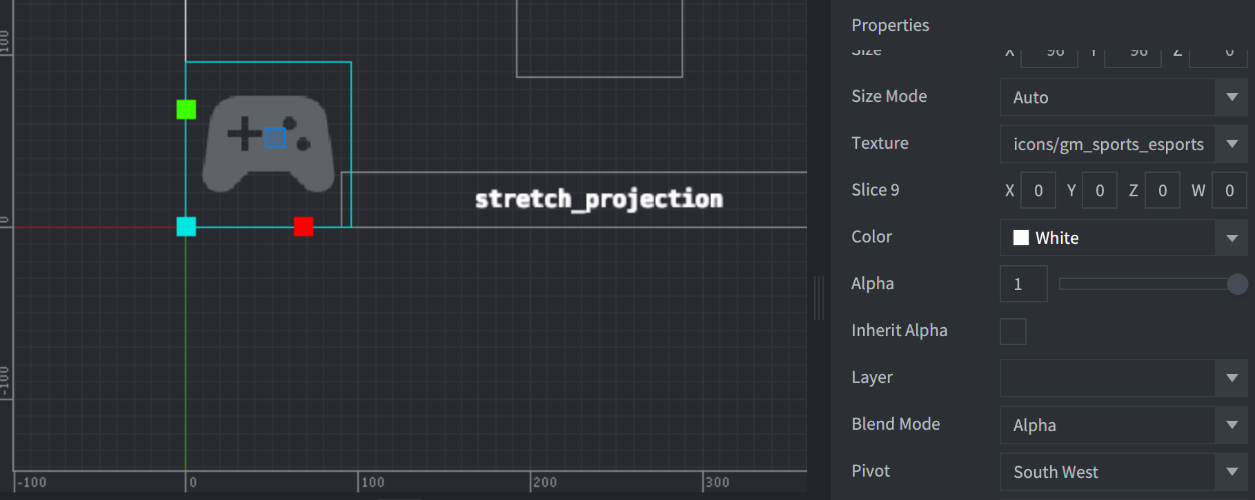
In the following example, the controller icon GUI node in the bottom-left has a
Position of 0,0 and Pivot set to Center.
CenterChanging Pivot to South West results in the following adjustment:
South WestGUI node adjust modes
GUI nodes may be resized when the display resolution differs from the base
project resolution. The Adjust Mode property controls the scaling behavior
of the node content. Adjust Mode has three settings: Fit, Zoom, and
Stretch.
Fit
The Fit setting preserves the aspect ratio of the node content. The content is
scaled to match either the width or height of the node’s resized bounds
rectangle. The axis chosen is the one with the smaller difference. This ensures
the content fits inside the bounds rectangle at its original aspect ratio.
Zoom
The Zoom setting also preserves the aspect ratio of the node content. Like the
Fit setting, Zoom scales the content to match either the width or height of
the node’s resized bounds rectangle. Unlike Fit, Zoom uses the axis with the
larger difference from the original size as the match target. This means that
the scaled content may overflow the bounds rectangle.
The following shows an example of two GUI nodes with different Adjust Mode
settings. The bottom-left controller icon has an Adjust Mode of Fit, while
the top-right controller icon has an Adjust Mode of Zoom.
Stretch
The Stretch setting scales the node content to exactly match the node’s
resized bounds rectangle. The original aspect ratio is not preserved.
GUI layouts
Defold has an alternative method for adapting GUI layouts to different screen resolutions: Layouts. Layouts can be added to a GUI scene to override the default GUI node properties. A Layout is associated with a specific screen resolution. When multiple Layouts are available, Defold will choose the Layout that most closely matches the actual screen resolution. The default position, size, scale, or graphic resource used by a GUI node can all be overridden by a Layout.